Guide to Steering Bushing Replacement
by Greg Ford
The replacement of the steering bushing on the passenger side of the steering rack is
not that difficult. In fact, you are not replacing the bushing inside the steering rack housing, but sliding
a new one next to it. It can be accessed by taking the passenger front tire off. However, using a lift is easier.
At our tech session we used a lift.
The following is a supplement and meant to clarify the instructions provided with the steering bushing replacement kit.
This is the procedure used at the TPOC tech session:
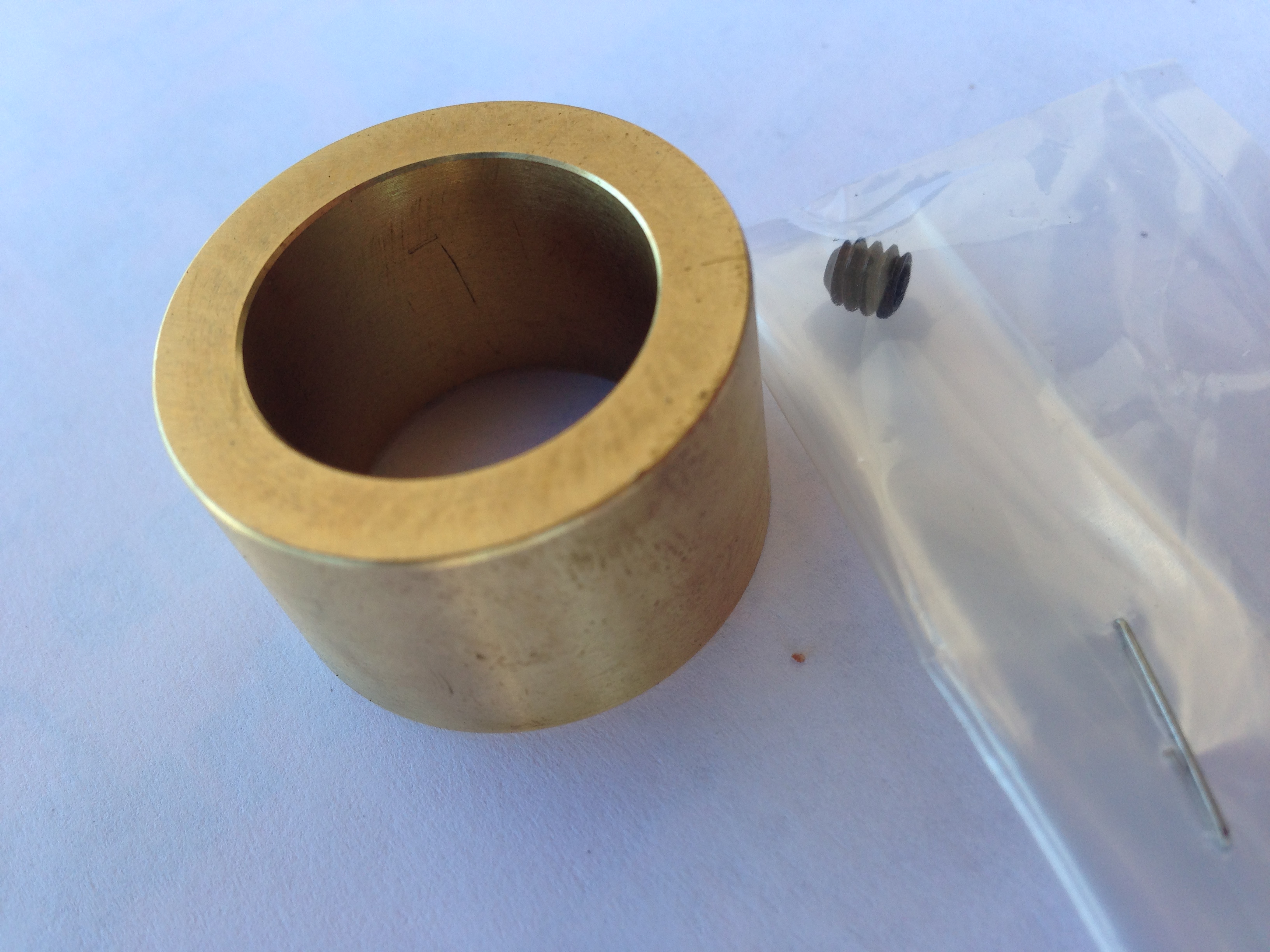
We purchased a bushing kit from a Pantera vendor. The kit includes a bushing, a 10-24 set screw, and instructions. Be sure your kit is the press fit type which has an outside diameter of 1.2165"
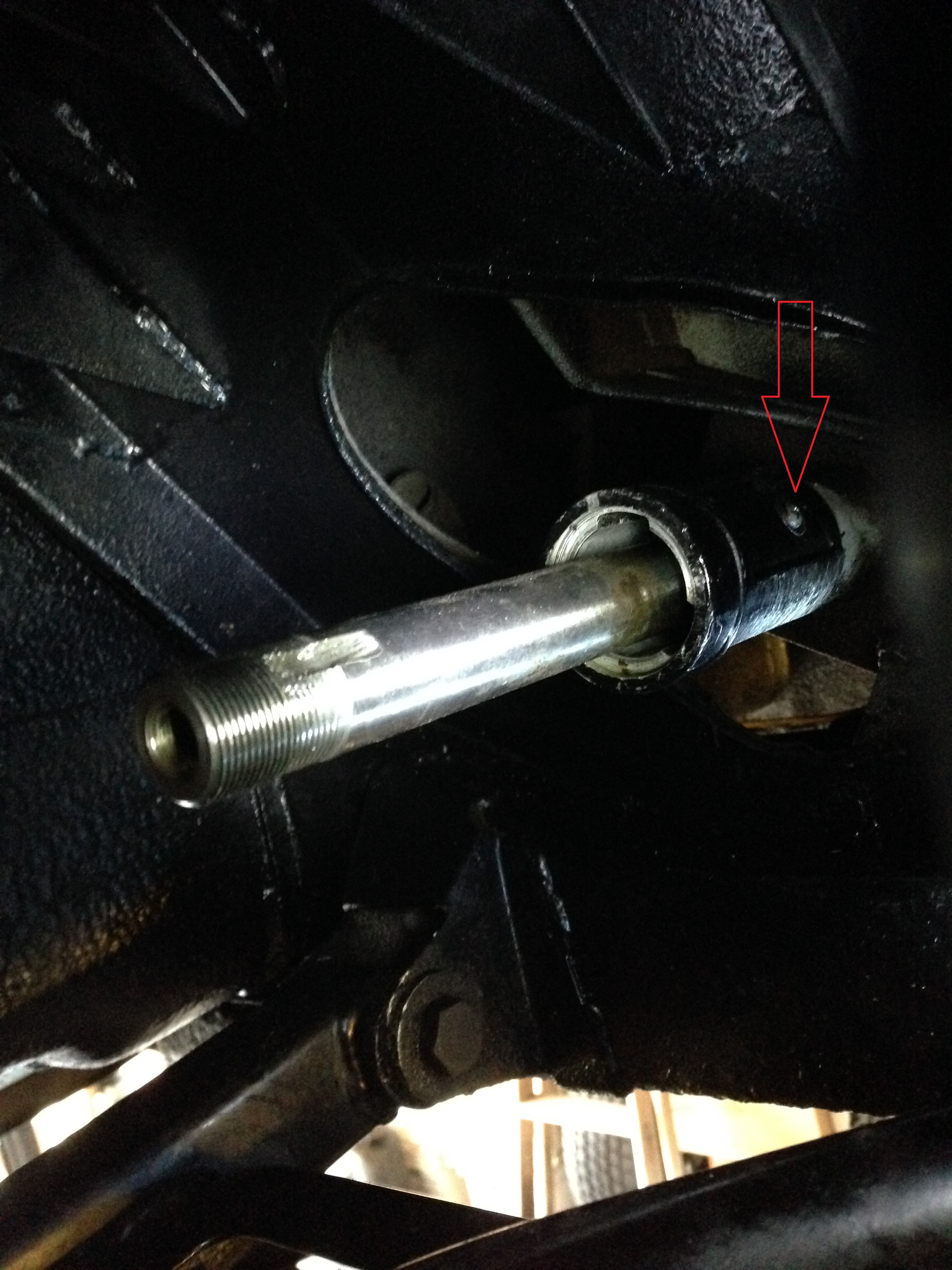
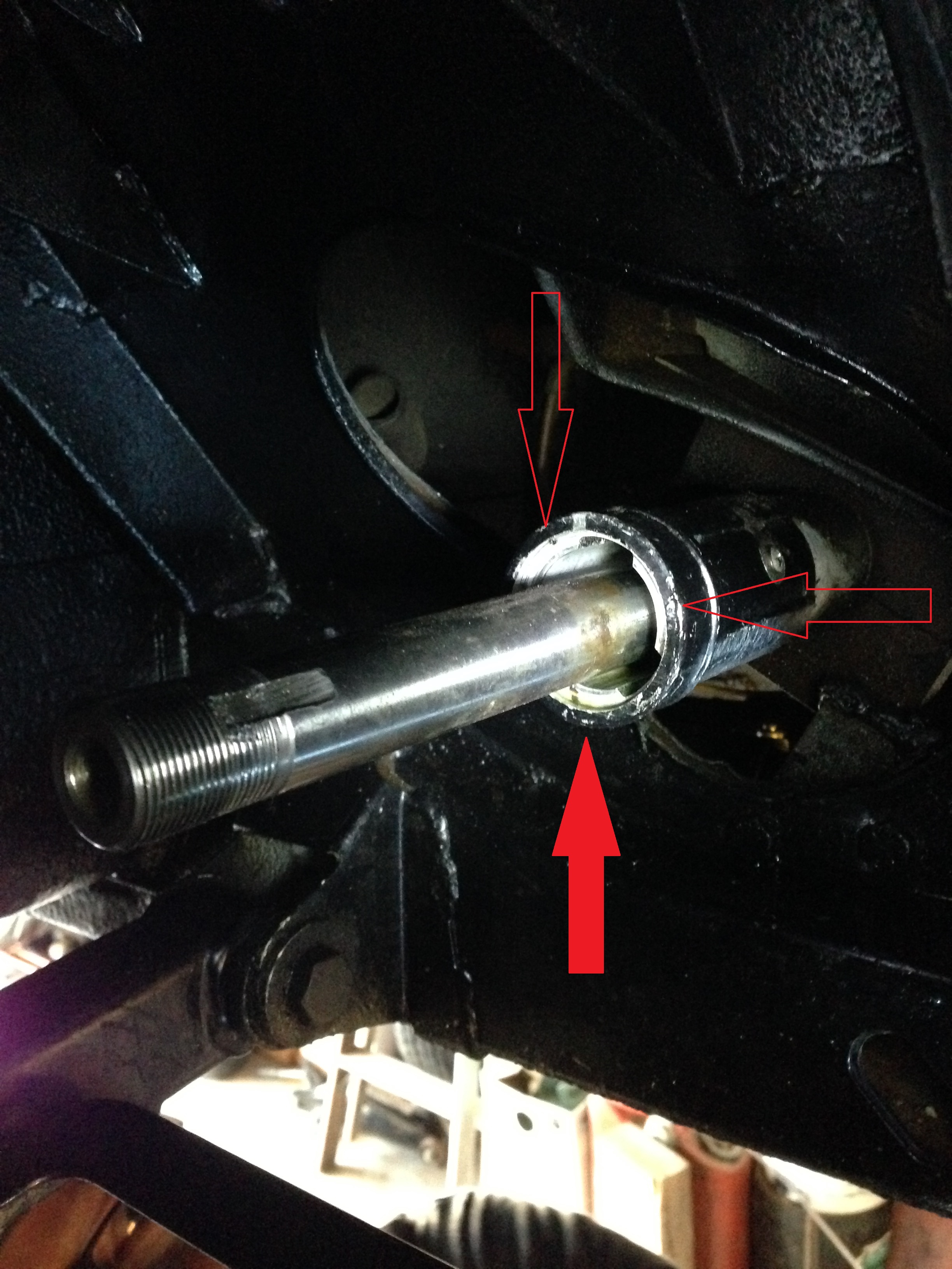
The picture below shows the rack with the ball nut and lock ring removed. Note the arrow pointing to a Phillips screw which is holding the original factory bushing. Do not remove this. If your rack has had a previous replacement bushing, you will be able to see it at the end of the housing. You may also see a set screw someplace around the housing, about 1 1/2 inches from the end of the housing.
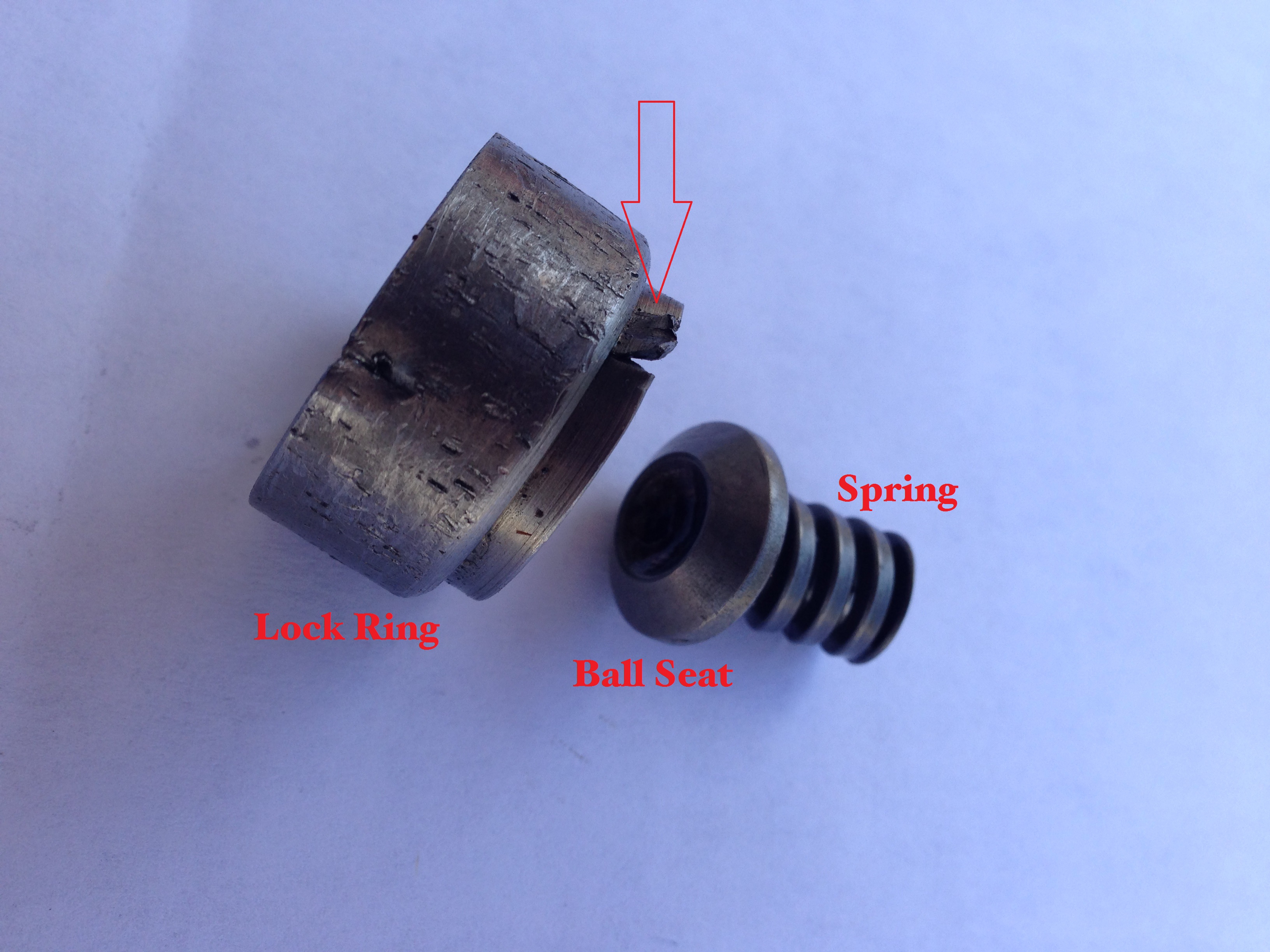
This picture shows the lock ring and the ball seat and spring. There is a machined slot in the rack shaft. We pried the lip (see arrow) of the lock ring up and out of the slot. Take your time when prying the lock ring and be sure to get it completely out of the slot. If you do not get the lock ring out of the slot, it will ruin the threads of the rack shaft as you unscrew it. You will then be unable to screw the lock ring back on. Unfortunately this happened to us.
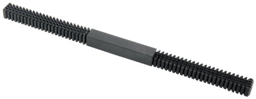
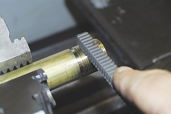
If the threads on the rack shaft have been damaged, they can be repaired. The threads on our cars are 7/8"-20. That is 20 threads per inch. The one picture shows a thread file that can be purchased for around $18.00 and the other picture shows how to run it across the threads. This is what we had to do and repairing the threads took under 10 minutes.
This picture shows another angle of the lock ring. The arrow is pointing to the other side that also had to be pried out of the ball nut. You can see we did a better job of lifting the metal.

Shown below is the unassembled ball nut on the tie rod shaft. The rubber splash boot is behind the ball nut.

There are three sections around the housing that are noticeably thicker (see arrows). You will be drilling one hole for the 10-24 set screw in one of these sections. The instructions show the hole should be drilled at the 11 o'clock position and the factory chose the 2 o'clock position. We chose the 6 o'clock position because with the rack in the car, this is the only spot we could reach with a drill motor. We used Locktite to hold the set screw in because it is our belief gravity could work the screw out.
This picture shows the tapped hole we put in the bottom of the rack.

The new bushing ready to be pressed in.

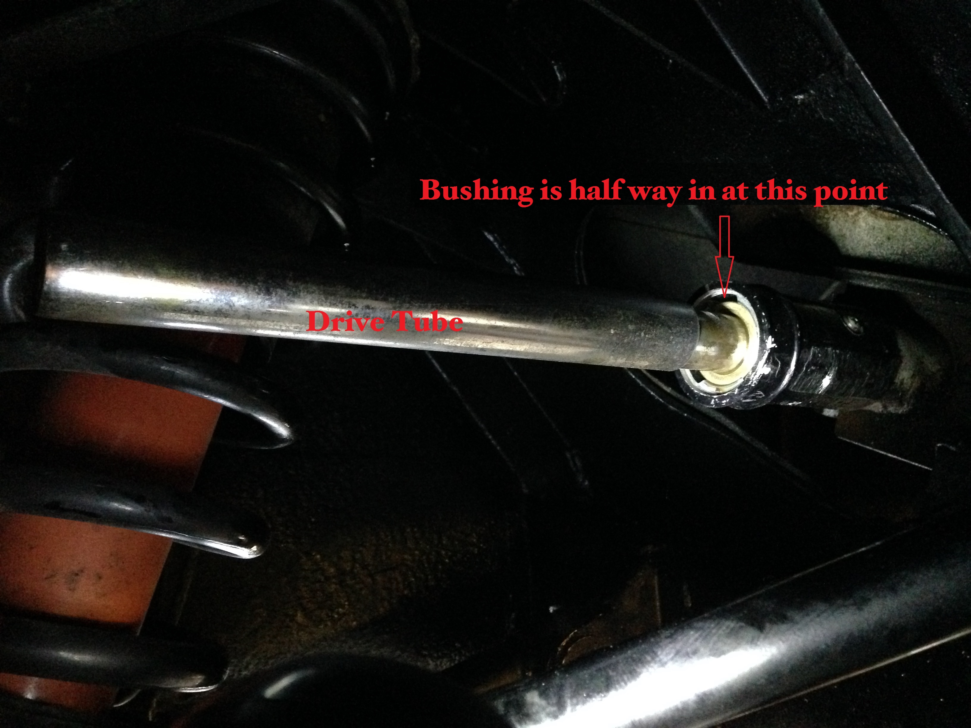
To drive the new bushing into the housing, we used a piece of tubing which was large enough to go over the rack shaft, but small enough to go into the housing. A light tap with a hammer easily drove the new bushing flush against the original bushing.
9/19/2015